Building a Perception Pipeline
In this exercise, we will fill in the appropriate pieces of code to build a perception pipeline. The end goal will be to broadcast a transform with the pose information of the object of interest.
Prepare New Workspace:
We will create a new catkin workspace, since this exercise does not overlap with the previous exercises.
Disable automatic sourcing of your previous catkin workspace:
gedit ~/.bashrccomment out (#) the last line, sourcing your
~/catkin_ws/devel/setup.bashNote
This means you’ll need to manually source the setup file from your new catkin workspace in each new terminal window.
- Close gedit and source ROS into your environment
source /opt/ros/kinetic/setup.bashCopy the template workspace layout and files:
cp -r ~/industrial_training/exercises/5.1/template_ws ~/perception_ws
cd ~/perception_ws/
Initialize and Build this new workspace
catkin init
catkin build
Source the workspace
source ~/perception_ws/devel/setup.bash
Copy the PointCloud file from prior Exercise 4.2 to your home directory (~):
cp ~/industrial_training/exercises/4.2/table.pcd ~
Import the new workspace into your QTCreator IDE:
- In QTCreator: File -> New File or Project -> Other Project -> ROS Workspace -> ~/perception_ws
Intro (Review Existing Code)
Most of the infrastructure for a ros node has already been completed for you; the focus of this exercise is the perception algorithms/pipleline. The CMakelists.txt and package.xml are complete and an executable has been provided. You could run the executable as is, but you would get errors. At this time we will explore the source code that has been provided - browse the provided perception_node.cpp file. The following are highlights of what is included.
- Headers:
- You will have to uncomment the PCL related headers as you go
- int main():
- The
mainfunction has been provided along with a while loop within the main function
- The
- ROS initialization:
- Both
ros::initandros::NodeHandlehave been called/initialized. Additionally there is a private nodehandle to use if you need to get parameters from a launch file within the node’s namespace.
- Both
- Set up parameters:
- Currently there are three string parameters included in the example: the world frame, the camera frame and the topic being published by the camera. It would be easy to write up a few
nh.getParamlines which would read these parameters in from a launch file. If you have the time, you should set this up because there will be many parameters for the pcl methods that would be better adjusted via a launch file than hardcoded.
- Currently there are three string parameters included in the example: the world frame, the camera frame and the topic being published by the camera. It would be easy to write up a few
- Set up publishers:
- Two publishers have been set up to publish ros messages for point clouds. It is often useful to visualize your results when working with image or point cloud processing.
- Listen for PointCloud2 (within while loop):
- Typically one would listen for a ros message using the ros subscribe method with a callback function, as done here. However it is often useful to do this outside of a callback function, so we show an example of listening for a message using
ros::topic::waitForMessage.
- Typically one would listen for a ros message using the ros subscribe method with a callback function, as done here. However it is often useful to do this outside of a callback function, so we show an example of listening for a message using
- Transform PointCloud2 (within while loop):
- While we could work in the camera frame, things are more understandable/useful if we are looking at the points of a point cloud in an xyz space that makes more sense with our environment. In this case we are transforming the points from the camera frame to a world frame.
- Convert PointCloud2 (ROS to PCL) (within while loop)
- Convert PointCloud2 (PCL to ROS) and publish (within while loop):
- This step is not necessary, but visualizing point cloud processing results is often useful, so conversion back into a ROS type and creating the ROS message for publishing is done for you.
So it seems that a lot has been done! Should be easy to finish up. All you need to do is fill in the middle section.
Primary Task: Filling in the blanks
The task of filling in the middle section containing the perception algorithms is an iterative process, so each step has been broken up into its own sub-task.
Implement Voxel Filter
Uncomment the voxel_grid include header, near the top of the file.
Change code:
The first step in most point cloud processing pipelines is the voxel filter. This filter not only helps to downsample your points, but also eliminates any NAN values so that any further filtering or processing is done on real values. See PCL Voxel Filter Tutorial for hints, otherwise you can copy the below code snippet.
Within
perception_node.cpp, find section/* ======================================== * Fill Code: VOXEL GRID * ========================================*/
Copy and paste the following beneath that banner.
pcl::PointCloud<pcl::PointXYZ>::Ptr cloud_ptr (new pcl::PointCloud<pcl::PointXYZ> (cloud));
pcl::PointCloud<pcl::PointXYZ>::Ptr cloud_voxel_filtered (new pcl::PointCloud<pcl::PointXYZ> ());
pcl::VoxelGrid<pcl::PointXYZ> voxel_filter;
voxel_filter.setInputCloud (cloud_ptr);
voxel_filter.setLeafSize (float(0.002), float(0.002), float(0.002));
voxel_filter.filter (*cloud_voxel_filtered);
Update Publisher Within
perception_node.cpp, find section/* ======================================== * CONVERT POINTCLOUD PCL->ROS * PUBLISH CLOUD * Fill Code: UPDATE AS NECESSARY * ========================================*/
Uncomment
pcl::toROSMsg, and replace*cloud_ptrwith*cloud_voxel_filteredAfter each new update, we’ll be swapping out which point-cloud is published for rviz viewing
Note
If you have the time/patience, I would suggest creating a ros publisher for each type of filter. It is often useful to view the results of multiple filters at once in Rviz and just toggle different clouds.
Compile
catkin build
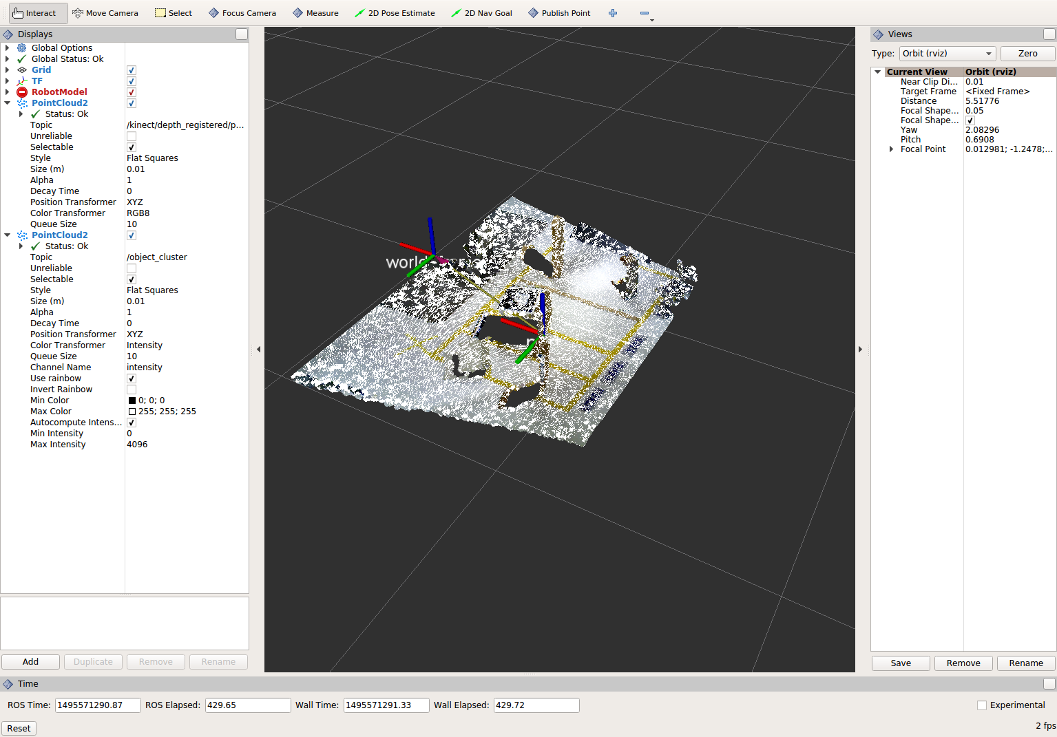
Viewing Results
Run the (currently small) perception pipeline. Note: In rviz change the global frame to kinect_link.
cd ~
roscore
rosrun tf2_ros static_transform_publisher 0 0 0 0 0 0 world_frame kinect_link
rosrun pcl_ros pcd_to_pointcloud table.pcd 0.1 _frame_id:=kinect_link cloud_pcd:=kinect/depth_registered/points
rosrun rviz rviz
rosrun lesson_perception perception_node
View results
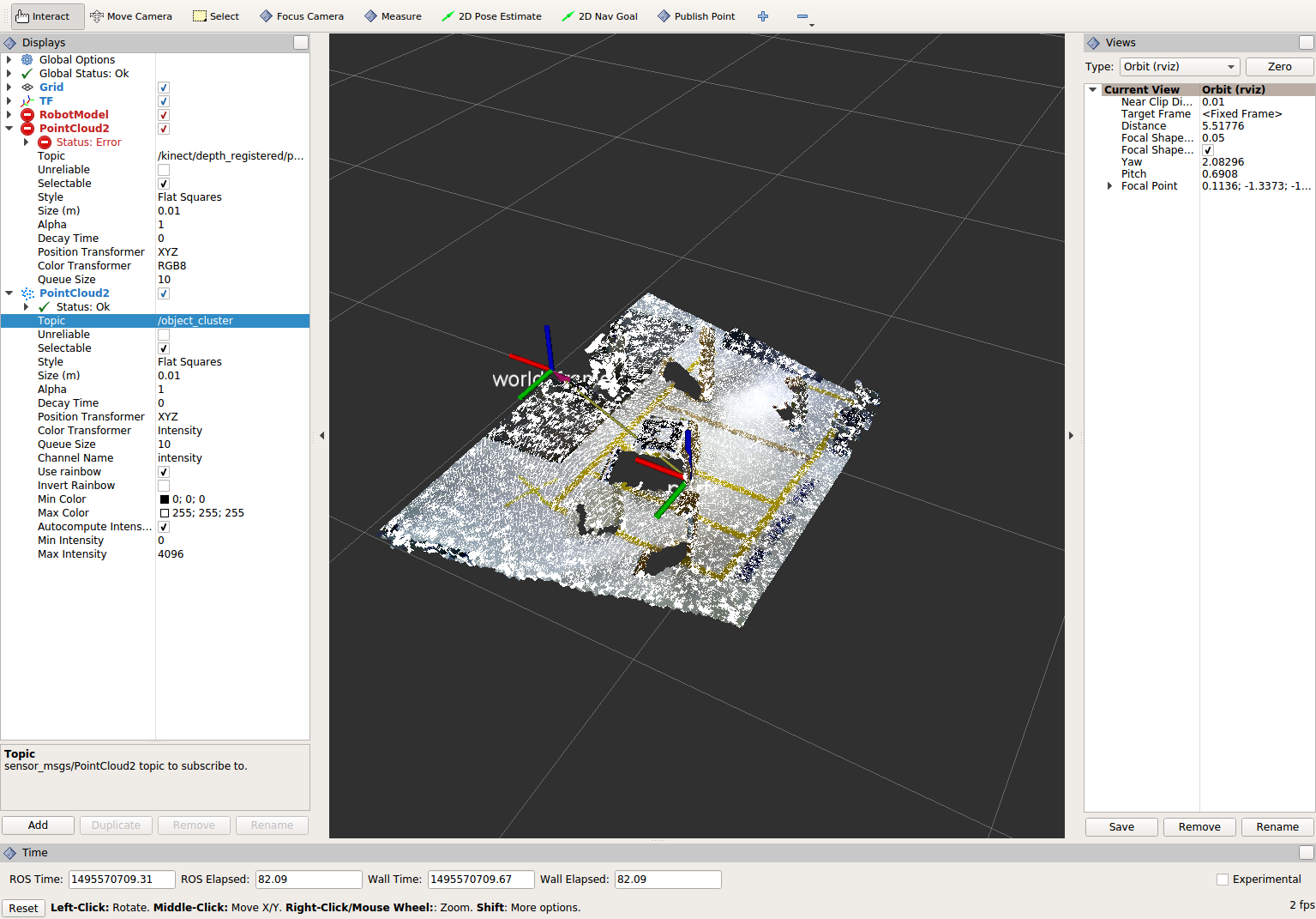
Within Rviz, add a PointCloud2 Display subscribed to the topic “object_cluster”. What you see will be the results of the voxel filter overlaid on the original point cloud (assuming you have completed exercise 4.2 and saved a new default config or saved a config for that exercise).
When you are done viewing the results, try changing the voxel filter size from 0.002 to 0.100 and view the results again. Reset the filter to 0.002 when done.
- To see the results of this change, use Ctrl+C to kill the perception node, re-build, and re-run the perception node.
Note
You do not need to stop any of the other nodes (rviz, ros, etc).
- When you are satisfied with the voxel filter, use Ctrl+C to stop the perception node.
Implement Pass-through Filters
As before, uncomment the PassThrough filter include-header near the top of the file.
Change code:
The next set of useful filtering to get the region of interest, is a series of pass-through filters. These filters crop your point cloud down to a volume of space (if you use x y and z filter). At this point you should apply a series of pass-through filters, one for each the x, y, and z directions. See PCL Pass-Through Filter Tutorial for hints, or use code below.
Within perception_node.cpp, find section
/* ========================================
 * Fill Code: PASSTHROUGH FILTER(S)
 * ========================================*/
Copy and paste the following beneath that banner.
pcl::PointCloud<pcl::PointXYZ> xf_cloud, yf_cloud, zf_cloud;
pcl::PassThrough<pcl::PointXYZ> pass_x;
pass_x.setInputCloud(cloud_voxel_filtered);
pass_x.setFilterFieldName("x");
pass_x.setFilterLimits(-1.0,1.0);
pass_x.filter(xf_cloud);

pcl::PointCloud<pcl::PointXYZ>::Ptr xf_cloud_ptr(new pcl::PointCloud<pcl::PointXYZ>(xf_cloud));
pcl::PassThrough<pcl::PointXYZ> pass_y;
pass_y.setInputCloud(xf_cloud_ptr);
pass_y.setFilterFieldName("y");
pass_y.setFilterLimits(-1.0, 1.0);
pass_y.filter(yf_cloud);

pcl::PointCloud<pcl::PointXYZ>::Ptr yf_cloud_ptr(new pcl::PointCloud<pcl::PointXYZ>(yf_cloud));
pcl::PassThrough<pcl::PointXYZ> pass_z;
pass_z.setInputCloud(yf_cloud_ptr);
pass_z.setFilterFieldName("z");
pass_z.setFilterLimits(-1.0, 1.0);
pass_z.filter(zf_cloud);
You can change the filter limit values to see different results.
Find the
pcl::toROSMsgcall where thepc2_cloudis populated. This is the point cloud that is published to RViz display. Replace the current cloud (*cloud_voxel_filter) with the final Passthrough Filter result (zf_cloud).Compile and run
catkin build
rosrun lesson_perception perception_node
View results
Within Rviz, compare PointCloud2 displays based on the
/kinect/depth_registered/points(original camera data) andobject_cluster(latest processing step) topics. Part of the original point cloud has been “clipped” out of the latest processing result.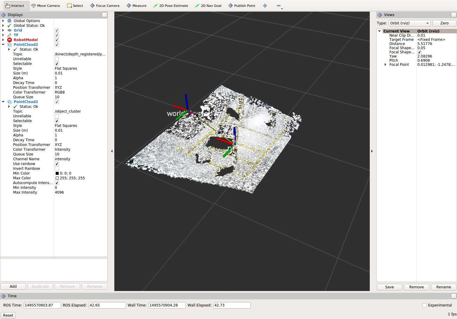
Note
Try modifying the X/Y/Z FilterLimits (e.g. +/- 0.5), re-build, and re-run. Observe the effects in rviz. When complete, reset the limite to +/- 1.0.
- When you are satisfied with the pass-through filter results, press Ctrl+C to kill the node. There is no need to close or kill the other terminals/nodes.
Plane Segmentation
Change code
This method is one of the most useful for any application where the object is on a flat surface. In order to isolate the objects on a table, you perform a plane fit to the points, which finds the points which comprise the table, and then subtract those points so that you are left with only points corresponding to the object(s) above the table. This is the most complicated PCL method we will be using and it is actually a combination of two: the RANSAC segmentation model, and the extract indices tool. An in depth example can be found on the PCL Plane Model Segmentation Tutorial; otherwise you can copy the below code snippet.
Within perception_node.cpp, find section:
/* ========================================
 * Fill Code: PLANE SEGEMENTATION
 * ========================================*/
Copy and paste the following beneath that banner.
pcl::PointCloud<pcl::PointXYZ>::Ptr cropped_cloud(new pcl::PointCloud<pcl::PointXYZ>(zf_cloud));
pcl::PointCloud<pcl::PointXYZ>::Ptr cloud_f (new pcl::PointCloud<pcl::PointXYZ>);
pcl::PointCloud<pcl::PointXYZ>::Ptr cloud_filtered (new pcl::PointCloud<pcl::PointXYZ>);
pcl::PointCloud<pcl::PointXYZ>::Ptr cloud_plane (new pcl::PointCloud<pcl::PointXYZ> ());
// Create the segmentation object for the planar model and set all the parameters
pcl::SACSegmentation<pcl::PointXYZ> seg;
pcl::PointIndices::Ptr inliers (new pcl::PointIndices);
pcl::ModelCoefficients::Ptr coefficients (new pcl::ModelCoefficients);
seg.setOptimizeCoefficients (true);
seg.setModelType (pcl::SACMODEL_PLANE);
seg.setMethodType (pcl::SAC_RANSAC);
seg.setMaxIterations (200);
seg.setDistanceThreshold (0.004);
// Segment the largest planar component from the cropped cloud
seg.setInputCloud (cropped_cloud);
seg.segment (*inliers, *coefficients);
if (inliers->indices.size () == 0)
{
  ROS_WARN_STREAM ("Could not estimate a planar model for the given dataset.") ;
  //break;
}
Once you have the inliers (points which fit the plane model), then you can extract the indices within the pointcloud data structure of the points which make up the plane.
// Extract the planar inliers from the input cloud
pcl::ExtractIndices<pcl::PointXYZ> extract;
extract.setInputCloud (cropped_cloud);
extract.setIndices(inliers);
extract.setNegative (false);

// Get the points associated with the planar surface
extract.filter (*cloud_plane);
ROS_INFO_STREAM("PointCloud representing the planar component: " << cloud_plane->points.size () << " data points." );
Then of course you can subtract or filter out these points from the cloud to get only points above the plane.
// Remove the planar inliers, extract the rest
extract.setNegative (true);
extract.filter (*cloud_f);
Find the
pcl::toROSMsgcall where thepc2_cloudis populated. This is the point cloud that is published to RViz display. Replace the current cloud (zf_cloud) with the plane-fit outliers result (*cloud_f).- Compile and run, as in previous steps.
Did you forget to uncomment the new headers used in this step?
Evaluate Results
Within Rviz, compare PointCloud2 displays based on the
/kinect/depth_registered/points(original camera data) andobject_cluster(latest processing step) topics. Only points lying above the table plane remain in the latest processing result.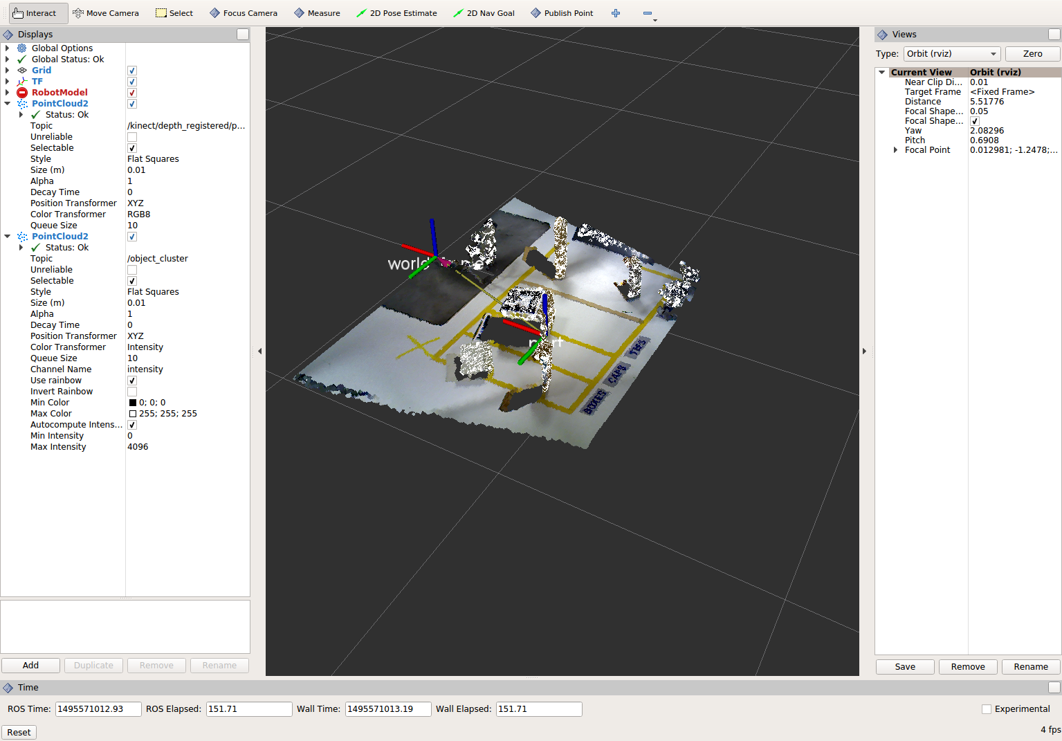
When you are done viewing the results you can go back and change the”setMaxIterations” and “setDistanceThreshold” values to control how tightly the plane-fit classifies data as inliers/outliers, and view the results again. Try using values of
MaxIterations=100andDistanceThreshold=0.010When you are satisfied with the plane segmentation results, use Ctrl+C to kill the node. There is no need to close or kill the other terminals/nodes.
Euclidean Cluster Extraction (optional, but recommended)
Change code
This method is useful for any application where there are multiple objects. This is also a complicated PCL method. An in depth example can be found on the PCL Euclidean Cluster Extration Tutorial.
Within perception_node.cpp, find section
/* ========================================
 * Fill Code: EUCLIDEAN CLUSTER EXTRACTION (OPTIONAL/RECOMMENDED)
 * ========================================*/
Follow along with the PCL tutorial, insert code in this section.
Copy and paste the following beneath the banner.
// Creating the KdTree object for the search method of the extraction
pcl::search::KdTree<pcl::PointXYZ>::Ptr tree (new pcl::search::KdTree<pcl::PointXYZ>);
*cloud_filtered = *cloud_f;
tree->setInputCloud (cloud_filtered);

std::vector<pcl::PointIndices> cluster_indices;
pcl::EuclideanClusterExtraction<pcl::PointXYZ> ec;
ec.setClusterTolerance (0.01); // 2cm
ec.setMinClusterSize (300);
ec.setMaxClusterSize (10000);
ec.setSearchMethod (tree);
ec.setInputCloud (cloud_filtered);
ec.extract (cluster_indices);

std::vector<sensor_msgs::PointCloud2::Ptr> pc2_clusters;
std::vector<pcl::PointCloud<pcl::PointXYZ>::Ptr > clusters;
for (std::vector<pcl::PointIndices>::const_iterator it = cluster_indices.begin (); it != cluster_indices.end (); ++it)
{
  pcl::PointCloud<pcl::PointXYZ>::Ptr cloud_cluster (new pcl::PointCloud<pcl::PointXYZ>);
  for (std::vector<int>::const_iterator pit = it->indices.begin (); pit != it->indices.end (); pit++)
    cloud_cluster->points.push_back(cloud_filtered->points[*pit]);
  cloud_cluster->width = cloud_cluster->points.size ();
  cloud_cluster->height = 1;
  cloud_cluster->is_dense = true;
  std::cout << "Cluster has " << cloud_cluster->points.size() << " points.\n";
  clusters.push_back(cloud_cluster);
  sensor_msgs::PointCloud2::Ptr tempROSMsg(new sensor_msgs::PointCloud2);
  pcl::toROSMsg(*cloud_cluster, *tempROSMsg);
  pc2_clusters.push_back(tempROSMsg);
}
Find the
pcl::toROSMsgcall where thepc2_cloudis populated. This is the point cloud that is published to RViz display. Replace the current cloud (*cloud_f) with the largest cluster (*(clusters.at(0))).Compile and run, as in previous steps.
View results in rviz. Experiment with
setClusterTolerance,setMinClusterSize, andsetMaxClusterSizeparameters, observing their effects in rviz.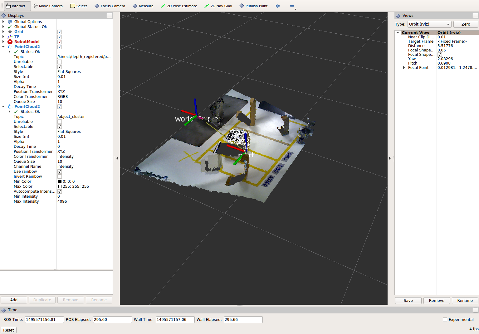
When you are satisfied with the cluster extraction results, use Ctrl+C to kill the node. There is no need to close or kill the other terminals/nodes.
Create a CropBox Filter
Change code
This method is similar to the pass-through filter from Sub-Task 2, but instead of using three pass-through filters in series, you can use one CropBox filter. Documentation on the CropBox filter and necessary header file can be found here.
Within perception_node.cpp, find section
/* ========================================
 * Fill Code: CROPBOX (OPTIONAL)
 * Instead of three passthrough filters, the cropbox filter can be used
 * The user should choose one or the other method
 * ========================================*/
This CropBox filter should replace your passthrough filters, you may delete or comment the passthrough filters. There is no PCL tutorial to guide you, only the PCL documentation at the link above. The general setup will be the same (set the output, declare instance of filter, set input, set parameters, and filter).
Set the output cloud:
pcl::PointCloud<pcl::PointXYZ> xyz_filtered_cloud;
Declare instance of filter:
pcl::CropBox<pcl::PointXYZ> crop;
Set input:
crop.setInputCloud(cloud_voxel_filtered);
Set parameters - looking at documentation, CropBox takes an Eigen Vector4f as inputs for max and min values:
Eigen::Vector4f min_point = Eigen::Vector4f(-1.0, -1.0, -1.0, 0);
Eigen::Vector4f max_point = Eigen::Vector4f(1.0, 1.0, 1.0, 0);
crop.setMin(min_point);
crop.setMax(max_point);
Filter:
crop.filter(xyz_filtered_cloud);
If you delete or comment the passthrough filters and have already written the plane segmentation code, then make sure you update the name of the cloud you are passing into the plane segmentation. Replace zf_cloud with xyz_filtered_cloud:
pcl::PointCloud<pcl::PointXYZ>::Ptr cropped_cloud(new pcl::PointCloud<pcl::PointXYZ>(xyz_filtered_cloud));
Find the
pcl::toROSMsgcall where thepc2_cloudis populated. This is the point cloud that is published to RViz display. Replace the current cloud with the new filtered results (xyz_filtered_cloud).Compile and run, as in previous steps
The following image of the CropBox filter in use will closely resemble the Plane Segmentation filter image.
Create a Statistical Outlier Removal
Change code
This method does not necessarily add complexity or information to our end result, but it is often useful. A tutorial can be found here.
Within perception_node.cpp, find section
/* ========================================
 * Fill Code: STATISTICAL OUTLIER REMOVAL (OPTIONAL)
 * ========================================*/
The general setup will be the same (set the output, declare instance of filter, set input, set parameters, and filter).
Set the output cloud:
pcl::PointCloud<pcl::PointXYZ>::Ptr cluster_cloud_ptr= clusters.at(0);
pcl::PointCloud<pcl::PointXYZ>::Ptr sor_cloud_filtered(new pcl::PointCloud<pcl::PointXYZ>);
Declare instance of filter:
pcl::StatisticalOutlierRemoval<pcl::PointXYZ> sor;
Set input:
sor.setInputCloud (cluster_cloud_ptr);
Set parameters - looking at documentation, S.O.R. uses the number of neighbors to inspect and the standard-deviation threshold to use for outlier rejection:
sor.setMeanK (50);
sor.setStddevMulThresh (1.0);
Filter:
sor.filter (*sor_cloud_filtered);
Find the
pcl::toROSMsgcall where thepc2_cloudis populated. Replace the current cloud with the new filtered results (*sor_cloud_filtered).Compile and run, as in previous steps

Create a Broadcast Transform
While this is not a filter method, it demonstrates how to publish the results of a processing pipeline for other nodes to use. Often, the goal of a processing pipeline is to generate a measurement, location, or some other message for other nodes to use. This sub-task broadcasts a TF transform to define the location of the largest box on the table. This transform could be used by other nodes to identify the position/orientation of the box for grasping.
Change/Insert code
Within perception_node.cpp, find section
/* ========================================
 * BROADCAST TRANSFORM (OPTIONAL)
 * ========================================*/
Follow along with the ROS tutorial. The important modifications to make are within the setting of the position and orientation information (setOrigin( tf::Vector3(msg->x, msg->y, 0.0) ), and setRotation(q) ). Create a transform:
static tf::TransformBroadcaster br;
tf::Transform part_transform;

//Here in the tf::Vector3(x,y,z) x,y, and z should be calculated based on the pointcloud filtering results
part_transform.setOrigin( tf::Vector3(sor_cloud_filtered->at(1).x, sor_cloud_filtered->at(1).y, sor_cloud_filtered->at(1).z) );
tf::Quaternion q;
q.setRPY(0, 0, 0);
part_transform.setRotation(q);
Remember that when you set the origin or set the rpy, this is where you should use the results from all the filters you’ve applied. At this point the origin is set arbitrarily to the first point within. Broadcast that transform:
br.sendTransform(tf::StampedTransform(part_transform, ros::Time::now(), world_frame, "part"));
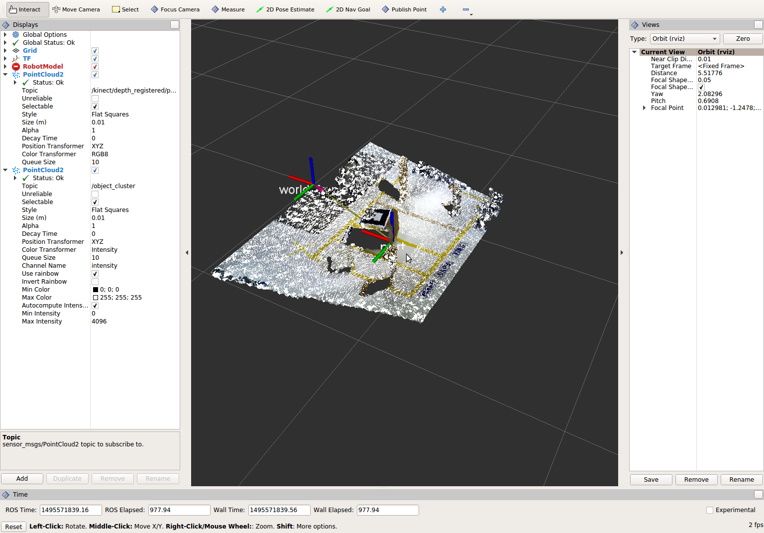
Compile and Run as usual. In this case, add a TF display to Rviz and observe the new “part” transform located at the top of the box.
Create a Polygonal Segmentation
When using sensor data for collision detection, it is sometimes necessary to exclude “known” objects from the scene to avoid interference from these objects. MoveIt! contains methods for masking out a robot’s own geometry as a “Self Collision” filtering feature. This example shows how to do something similar using PCL’s Polygonal Segmentation filtering.
Change code
This method is similar to the plane segmentation from Sub-Task 3, but instead of segmenting out a plane, you can segment and remove a prism. Documentation on the PCL Polygonal Segmentation can be found here and here. The goal in this sub-task is to remove the points that correspond to a known object (e.g. the box we detected earlier). This particular filter is applied to the entire point cloud (original sensor data), but only after we’ve already completed the processing steps to identify the position/orientation of the box.
Within perception_node.cpp, add
#include <tf_conversions/tf_eigen.h>and find section/* ======================================== * Fill Code: POLYGONAL SEGMENTATION (OPTIONAL) * ========================================*/
Set the input cloud:
pcl::PointCloud<pcl::PointXYZ>::Ptr sensor_cloud_ptr (new pcl::PointCloud<pcl::PointXYZ>(cloud));
pcl::PointCloud<pcl::PointXYZ>::Ptr prism_filtered_cloud (new pcl::PointCloud<pcl::PointXYZ>);
pcl::PointCloud<pcl::PointXYZ>::Ptr pick_surface_cloud_ptr(new pcl::PointCloud<pcl::PointXYZ>);
Declare instance of filter:
pcl::ExtractPolygonalPrismData<pcl::PointXYZ> prism;
Set extraction indices:
pcl::ExtractIndices<pcl::PointXYZ> extract_ind;
Set input and output:
prism.setInputCloud(sensor_cloud_ptr);
pcl::PointIndices::Ptr pt_inliers (new pcl::PointIndices());
Set parameters - looking at documentation, ExtractPolygonalPrismData uses a pointcloud defining the polygon vertices as its input.
// create prism surface
double box_length=0.25;
double box_width=0.25;
pick_surface_cloud_ptr->width = 5;
pick_surface_cloud_ptr->height = 1;
pick_surface_cloud_ptr->points.resize(5);

pick_surface_cloud_ptr->points[0].x = 0.5f*box_length;
pick_surface_cloud_ptr->points[0].y = 0.5f*box_width;
pick_surface_cloud_ptr->points[0].z = 0;

pick_surface_cloud_ptr->points[1].x = -0.5f*box_length;
pick_surface_cloud_ptr->points[1].y = 0.5f*box_width;
pick_surface_cloud_ptr->points[1].z = 0;

pick_surface_cloud_ptr->points[2].x = -0.5f*box_length;
pick_surface_cloud_ptr->points[2].y = -0.5f*box_width;
pick_surface_cloud_ptr->points[2].z = 0;

pick_surface_cloud_ptr->points[3].x = 0.5f*box_length;
pick_surface_cloud_ptr->points[3].y = -0.5f*box_width;
pick_surface_cloud_ptr->points[3].z = 0;

pick_surface_cloud_ptr->points[4].x = 0.5f*box_length;
pick_surface_cloud_ptr->points[4].y = 0.5f*box_width;
pick_surface_cloud_ptr->points[4].z = 0;

Eigen::Affine3d eigen3d;
tf::transformTFToEigen(part_transform,eigen3d);
pcl::transformPointCloud(*pick_surface_cloud_ptr,*pick_surface_cloud_ptr,Eigen::Affine3f(eigen3d));

prism.setInputPlanarHull( pick_surface_cloud_ptr);
prism.setHeightLimits(-10,10);
Segment:
prism.segment(*pt_inliers);
Remember that after you use the segmentation algorithme that you either want to include or exclude the segmented points using an index extraction.
Set input:
extract_ind.setInputCloud(sensor_cloud_ptr);
extract_ind.setIndices(pt_inliers);
This time, we invert the index extraction, so that we remove points inside the filter and keep points outside the filter.
extract_ind.setNegative(true);
Filter:
extract_ind.filter(*prism_filtered_cloud);
Find the
pcl::toROSMsgcall where thepc2_cloudis populated. This is the point cloud that is published to RViz display. Replace the current cloud with the new filtered results (*prism_filtered_cloud).Compile and run as before.
Note
Notice that the target box has been removed from the point cloud display.
Write a launch file
While this is not a filter method, it is useful when using PCL or other perception methods because of the number of parameters used in the different methods.
Change/Insert code
If you are really awesome and read the Task 1 write-up thoroughly, you will note that it was suggested that you put your parameters in one place.
Within perception_node.cpp, find section
/*
 * SET UP PARAMETERS (COULD TO BE INPUT FROM LAUNCH FILE/TERMINAL)
 */
Ideally, as the given parameter examples showed, you would declare a parameter of a certain type (std::string frame;), then assign a value for that parameter (frame=”some_name”;). Below is an example of some of the parameters you could have set.
world_frame="kinect_link";
camera_frame="kinect_link";
cloud_topic="kinect/depth_registered/points";
voxel_leaf_size=0.002f;
x_filter_min=-2.5;
x_filter_max=2.5;
y_filter_min=-2.5;
y_filter_max=2.5;
z_filter_min=-2.5;
z_filter_max=1.0;
plane_max_iter=50;
plane_dist_thresh=0.05;
cluster_tol=0.01;
cluster_min_size=100;
cluster_max_size=50000;
If you took this step, you will be in great shape to convert what you have into something that can be input from a launch file, or yaml file. You could use the “getParam” method as described in this tutorial. But a better choice might be to use the param method, which returns a default value if the parameter is not found on the parameter server. Get params from ros parameter server/launch file, replacing your previous hardcoded values (but leave the variable declarations!)
cloud_topic = priv_nh_.param<std::string>("cloud_topic", "kinect/depth_registered/points");
world_frame = priv_nh_.param<std::string>("world_frame", "kinect_link");
camera_frame = priv_nh_.param<std::string>("camera_frame", "kinect_link");
voxel_leaf_size = param<float>("voxel_leaf_size", 0.002);
x_filter_min = priv_nh_.param<float>("x_filter_min", -2.5);
x_filter_max = priv_nh_.param<float>("x_filter_max",  2.5);
y_filter_min = priv_nh_.param<float>("y_filter_min", -2.5);
y_filter_max = priv_nh_.param<float>("y_filter_max",  2.5);
z_filter_min = priv_nh_.param<float>("z_filter_min", -2.5);
z_filter_max = priv_nh_.param<float>("z_filter_max",  2.5);
plane_max_iter = priv_nh_.param<int>("plane_max_iterations", 50);
plane_dist_thresh = priv_nh_.param<float>("plane_distance_threshold", 0.05);
cluster_tol = priv_nh_.param<float>("cluster_tolerance", 0.01);
cluster_min_size = priv_nh_.param<int>("cluster_min_size", 100);
cluster_max_size = priv_nh_.param<int>("cluster_max_size", 50000);
Write launch file.
Using gedit or some other text editor, make a new file (‘’lesson_perception/launch/processing_node.launch’’) and put the following in it.
<launch>
  <node name="processing_node" pkg="lesson_perception" type="perception_node" output="screen">
    <rosparam>
      cloud_topic: "kinect/depth_registered/points"
      world_frame: "world_frame"
      camera_frame: "kinect_link"
      voxel_leaf_size: 0.001 <!-- mm -->
      x_filter_min: -2.5 <!-- m -->
      x_filter_max: 2.5 <!-- m -->
      y_filter_min: -2.5 <!-- m -->
      y_filter_max: 2.5 <!-- m -->
      z_filter_min: -2.5 <!-- m -->
      z_filter_max: 2.5 <!-- m -->
      plane_max_iterations: 100
      plane_distance_threshold: 0.03
      cluster_tolerance: 0.01
      cluster_min_size: 250
      cluster_max_size: 500000
    </rosparam>
  </node>
</launch>
Compile as usual…
But this time, run the new launch file that was created instead of using rosrun to start the processing node.
The results should look similar to previous runs. However, now you can edit these configuration parameters much easier! No recompile step is required; just edit the launch-file values and relaunch the node. In a real application, you could take this approach one step further and implement dynamic_reconfigure support in your node. That would allow you to see the results of parameter changes in RViz in real-time!
When you are satisfied with the results, go to each terminal and CTRL-C.
We’re all done! So it’s best to make sure everything is wrapped up and closed.